Question: Explain the underlying principle and working of an electric generator by drawing a labelled diagram. What is the function of brushes?
Answer:
AC generator
“AC generator” means “Alternating Current generator”. That is, an A C generator produces alternating current, which alternates (changes) in polarity continuously. We will now describe the construction an working of the A. C. generator or A. C. dynamo.
Construction of an AC generator
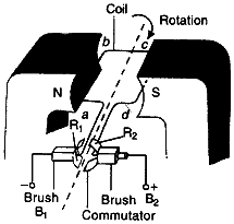
A simple AC generator consists of a rectangular coil ABCD that can be rotated rapidly between the poles N and S of a strong horseshoe type magnet M. The coil is made of a large number of turns of insulated copper wire. The ends A and D of the rectangular coil are connected to two circular pieces of copper metal called slip rings R1 and R2. As the slip rings R1 and R2 rotate with the coil, the two pieces of carbon called brushes, B1 and B2, keep contact with them. So, the current produced in the rotating coil can be tapped out through slip rings into the carbon brushes. From the carbon brushes B1 and B2 we take the current into various electrical appliances like radio, T. V., electric iron, bulbs, etc. But in this figure, we have shown only a galvanometer G connected the two carbon brushes.
Working of an AC generator
Suppose that the generator coil ABCD is initially in the horizontal position. Again suppose that he coil ABCD is being rotated in the anticlockwise direction between the poles N and S of a horseshoe type magnet.
(i) As the coil rotates in the anticlockwise direction, the side AB of the coil moves down cutting the magnetic lines of force near the N-pole of the magnet, and side CD moves up, cutting the lines of force near the S-pole of the magnet. Due to this, induced current is produced in the sides AB and DC of the coil. On applying Fleming’s right hand rule to the side AB and DC of the coil, we find that the currents are in the direction B to A and D to C respectively. Thus, the induced currents in the two sides of the coil are in the same direction, and we get an effective induced current in the direction BADC.

(ii) After half revolution, the sides AB and DC of the coil will interchange their positions. The side AB will come on the right hand side and DC will come on the left side. So, after half a revolution, side AB starts moving up and side DC starts coming down. As a result of this, the direction of induced current in each side of the coil is reversed after half a revolution. Since the direction of induced current in the coil is reversed after half revolution so the polarity (positive and negative) of the two ends of the coil also changes after half revolution. The end of coil which was positive in the first half of rotation becomes negative in the second in the second half. And the end which was negative in the first half revolution becomes positive in the second half of revolution. Thus, in 1 revolution of the coil, the current changes its direction 2 times.
The alternating current (AC) produced in India has a frequency of 50 Hz. That is, the coil is rotated at the rate of 50 revolutions per second. Since in 1 revolution of coil, the current changes its direction 2 times, so in 50 revolutions of coil, the current changes its direction 2 × 50 = 100 times. Thus, the AC supply in India changes its direction 100 times in 1 second. Another way of saying this is that the alternating current produced in India changes its direction every 1/100 second. That is, each terminal of the coil is positive (+) for 1/100 of a second and negative (-) for the next 1/100 of a second. This process is repeated again and again with the result that there is actually no positive and negative in an AC generator. We will now describe why the direction of induced current in the coil of an AC generator changes after every half revolution of the coil.
After every half revolution, each side of the generator coil starts moving in the opposite direction in the magnetic field. The side of the coil which was initially moving downwards in a magnetic field, after half revolution, it starts moving in opposite direction – upwards. Similarly the side of coil which was initially moving upwards, after half revolution, it starts moving downwards. Due to the change in the direction of motion of the two sides of the coil in the magnetic field after every half revolution, the direction of current produced in them also changes after every half revolution.
DC generator
“DC generator” means “Direct Current generator”. That is, a DC generator produces direct current and not alternating current. We will now describe the construction and working of DC generator or DC Dynamo.
Construction of a DC generator
A simple DC generator consists of a rectangular coil ABCD which cab be rotated rapidly between the poles N and S of a strong horse-shoe type magnet M. The generator coil is made of a large number of turns of insulated copper wire. The two ends of the coil are connected to the two copper half rings (or split rings) R1 and R2 of a commutator. There are two carbon brushes B1 and B2 which press lightly against the two half rings. When the coil is rotated, the two half rings R1 and R2 touch the two carbon brushes B1 and B2 one by one. So the current produced in the rotating coil can be tapped out through the commutator half rings into the carbon brushes. From the carbon brushes B1 and B2, we can take the current into the various electrical appliances like radio, T. V., electric iron, bulbs, etc. But in this figure, we have shown only a galvanometer G connected between the two carbon brushes. The galvanometer is a current detecting and current measuring instrument.
Working of a DC generator:
Suppose that the generator coil ABCD is initially in the horizontal position. Again suppose that he coil ABCD is being rotated in the anticlockwise direction between the poles N and S of a horseshoe type magnet.
(iii) As the coil rotates in the anticlockwise direction, the side AB of the coil moves down cutting the magnetic lines of force near the N-pole of the magnet, and side DC moves up, cutting the lines of force near the S-pole of the magnet. Due to this, induced current is produced in the sides AB and DC of the coil. On applying Fleming’s right hand rule to the side AB and DC of the coil we find that the currents in them are in the direction B to A and D to C respectively. Thus, the induced currents in the two sides of the coil are in the same direction, and we get an effective induced current in the direction BADC. Due to this the brush B1 becomes a positive (+) pole and brush B2 becomes negative (-) pole of the generator.
(iv) After half revolution, the sides AB and DC of the coil will interchange their positions. The side AB will come on the right hand side and start moving up whereas side DC will come on then the two commutator half rings R1 and R2 automatically change their contacts from one carbon brush to the other. Due to this change, the current keeps flowing in the same direction in the other circuits. The brush B1 always remaining positive terminal and brush B2 always remaining negative terminal of the generator. Thus, a D. C. generator supplies a current in one direction by the use of a commutator consisting of two, half-rings of copper. In the above discussion we have used the word D. C. generator everywhere. Please note that we can also write D. C. dynamo in place of D. C. generator.
Question: When does an electric short circuit occur?
Answer: Short circuiting If the plastic insulation of the live wire and neutral wire gets torn, then the two wires touch each other. This touching of the live wire and neutral wire directly is known as short-circuiting. The current passing through the circuit formed by these wires is very large and consequently a high heating effect is created which may lead to fire.
Question: What is the function of an earth wire? Why is it necessary to earth metallic appliances?
Answer: To avoid electric shocks, the metal body of an electrical device is ‘earthed’. A wire called ‘earth wire’ is used to connect the metal body of the electrical device to the earth, which is at zero potential. In household circuits, we have three wires, the live wire, the neutral wire and the earth wire. One end of the earth wire is connected to the device and the other end of the wire is connected to the earth. We now say that the device is “earthed” or “grounded”. Usually the three wires are connected to a three-pin plug. The neutral wire or the earth connection carries the high current to the earth from the device and prevents an electric shock.
 Class Notes NCERT Solutions for CBSE Students


